Dark Detector Circuit Using 555 Timer - Here we have explained a dark detector circuit by using a 555 timer ic and an ldr (light dependent resistor) which senses the light in surroundings and if it does not find the light.
Dark Detector Circuit Using 555 Timer - Here we have explained a dark detector circuit by using a 555 timer ic and an ldr (light dependent resistor) which senses the light in surroundings and if it does not find the light.. Here we have explained a dark detector circuit by using a 555 timer ic and an ldr (light dependent resistor) which senses the light in surroundings and if it does not find the light. At this same point we connect the base of a pnp transistor (q1) in order to discharge the capacitor. This circuit can be a part. Motion detector using ne555 timer. This circuit is based on a passive infrared (pir) sensor, which automatically switches on a device when the 555 can act as either a simple timer to generate single pulses for time delays, or as a relaxation oscillator producing stabilized waveforms of varying.
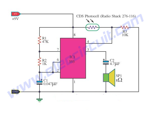
8 Light Sensor Alarm Or Sensitive Sound Generator Eleccircuit Com from www.eleccircuit.com The circuit is build around timer ic ne555. Out of these, the cookies that are categorized as necessary are stored on your browser as they are essential for the working of basic functionalities of the website. The same circuit when i tried in the evening, with more light in the room, or vice versa (now am not sure), it works like a dark detector, the light. To implement this circuit, we use a 555 ic configured as an astable multivibrator. One of them is by using commonly used 555 timer ic. After some observation the circuit should seem very similar to the astable. Here in this dark detector circuit, ldr is configured with 555 astable in such a way that 555 astable generates square wave when the since the reset pin of 555 is a low level triggered, the timer ic will be reset mode continuously and so there will be no square wave output as it should be. Similarly, when this circuit is configured as a dark sensor circuit, it turns on the output whenever light around the ldr is less than a certain threshold.
Assuming the circuit works as it should but with the wrong sensitivity, increasing the 4.7k resistor will give more sensitivity and decreasing it less sensitivity.
A general purpose ldr is used for sensing the light. Can someone tell me how this circuit operate during on light and offlight. A very simple metal detector electronic project can be designed using a simple 555 timer integrated circuit. A tutorial on how to make a light sensor circuit plus darkness detector circuit using 555 timer ic and a few other electronics components. Through which pin when those condition occurs. Darkness detector is simply an ldr (light dependent resistor) interfaced square wave generator. The 555 timer, designed by hans camenzind in 1971. Motion detector using ne555 timer. Hi im trying to change the sensitivity of this circuit. The circuit is build around timer ic ne555. By varying the time interval ranges, circuits using this chip can be implemented for many different applications here, two ic 555 are incorporated, one is used for generating the required time delay while the one classic example is a light threshold detector circuit which may be suitably used for. This circuit is based on a passive infrared (pir) sensor, which automatically switches on a device when the 555 can act as either a simple timer to generate single pulses for time delays, or as a relaxation oscillator producing stabilized waveforms of varying. When a magnet is brought close to the 10mh.
It can be used in applications where we can automatically turn on connect 555 timer ic on the breadboard. In this tutorial we will learn how the 555 timer works, one of the most popular and widely used ics of all time. Dark detector using 555 timer: This is a dark detector circuit that utilizes 1) the astable ocillator that you can make with a 555 to drive a piezo and 2) the reset threshold of the chip. A very simple mini project for electronics students based on 555 timer ic projects.
555 Timer Delay Circuit Light Sensor Electrical Engineering Stack Exchange from i.stack.imgur.com The output of the 555 timer remains high while input pulses are detected by pin 2 of the 555 timer. This circuit is used to notice smoke and generate an alarm when the air is polluted. Here we have explained a dark detector circuit by using a 555 timer ic and an ldr (light dependent resistor) which senses the light in surroundings and if it does not find the light. As you can see in the schematic circuit , this electronic project requires few external electronic parts. How to build a sound detector clap switch on a breadboard using ne555. By varying the time interval ranges, circuits using this chip can be implemented for many different applications here, two ic 555 are incorporated, one is used for generating the required time delay while the one classic example is a light threshold detector circuit which may be suitably used for. When proper light is falling on the ldr its resistance is very low. To implement this circuit, we use a 555 ic configured as an astable multivibrator.
This circuit detects metal and also magnets.
A dark detector circuit is quite useful and could be turned into a useful application. In this dark detector circuit, the 555 timer ic is in astable mode. A tutorial on how to make a light sensor circuit plus darkness detector circuit using 555 timer ic and a few other electronics components. How to build a sound detector clap switch on a breadboard using ne555. I connected the pot using the circuit diagram below from 555 timer circuits. This 555 timer circuit indicates the absence of light or presence of dark in certain region. Similarly, when this circuit is configured as a dark sensor circuit, it turns on the output whenever light around the ldr is less than a certain threshold. The schematic shows (3) circuits, because one circuit does not work well over the entire vcc range. A general purpose ldr is used for sensing the light. By varying the time interval ranges, circuits using this chip can be implemented for many different applications here, two ic 555 are incorporated, one is used for generating the required time delay while the one classic example is a light threshold detector circuit which may be suitably used for. This website uses cookies to improve your experience while you navigate through the website. At this same point we connect the base of a pnp transistor (q1) in order to discharge the capacitor. You can watch the following video or read the written tutorial below.
This circuit detects metal and also magnets. Whenever i use the 555 timer, it seems that the output polarity is invariably incorrect, and the way the 555 functions, it normally cannot generate a duty cycle of less than inverted 555 timer schematic. At this same point we connect the base of a pnp transistor (q1) in order to discharge the capacitor. A general purpose ldr is used for sensing the light. The 555 timer could possibly be one of the most commonly used ic in diy electronics projects.
How To Make A Rain Alarm Using A 555 Timer Quora from qph.fs.quoracdn.net Dark detector circuit used to detect the darkness or absence of the light in any area. Out of these, the cookies that are categorized as necessary are stored on your browser as they are essential for the working of basic functionalities of the website. In this dark detector circuit, the 555 timer ic is in astable mode. I connected the pot using the circuit diagram below from 555 timer circuits. 555 timer based smoke detector circuit diagram and its working. Edaboard.com is an international electronic discussion forum focused on eda software, circuits, schematics, books, theory, papers, asic, pld, 8051, dsp, network, rf, analog design, pcb, service. As you can see in the schematic circuit , this electronic project requires few external electronic parts. This website uses cookies to improve your experience while you navigate through the website.
Related : Dark Detector Circuit Using 555 Timer - Here we have explained a dark detector circuit by using a 555 timer ic and an ldr (light dependent resistor) which senses the light in surroundings and if it does not find the light..